Monday, November 29, 2010

USB Protocols- Beyond Logic Tutorial

This information is for my reference when I start communicating the PlayStation controller to the LabVIEW host (processing for the user interface). Information was obtained from http://www.beyondlogic.org/usbnutshell/usb3.shtml .

Unlike RS-232 and similar serial interfaces where the format of data being sent is not defined, USB is made up of several layers of protocols. While this sounds complicated, don’t give up now. Once you understand what is going on, you really only have to worry about the higher level layers. In fact most USB controller I.C.s will take care of the lower layer, thus making it almost invisible to the end designer.
Each USB transaction consists of a
    • Token Packet (Header defining what it expects to follow), an
    • Optional Data Packet, (Containing the payload) and a
    • Status Packet (Used to acknowledge transactions and to provide a means of error correction)
As we have already discussed, USB is a host centric bus. The host initiates all transactions. The first packet, also called a token is generated by the host to describe what is to follow and whether the data transaction will be a read or write and what the device’s address and designated endpoint is. The next packet is generally a data packet carrying the payload and is followed by an handshaking packet, reporting if the data or token was received successfully, or if the endpoint is stalled or not available to accept data.

Data on the USBus is transmitted LSBit first. USB packets consist of the following fields,
    • Sync
All packets must start with a sync field. The sync field is 8 bits long at low and full speed or 32 bits long for high speed and is used to synchronise the clock of the receiver with that of the transmitter. The last two bits indicate where the PID fields starts.
    • PID
PID stands for Packet ID. This field is used to identify the type of packet that is being sent. The following table shows the possible values.


There are 4 bits to the PID, however to insure it is received correctly, the 4 bits are complemented and repeated, making an 8 bit PID in total. The resulting format is shown below.


    • ADDR
The address field specifies which device the packet is designated for. Being 7 bits in length allows for 127 devices to be supported. Address 0 is not valid, as any device which is not yet assigned an address must respond to packets sent to address zero.
    • ENDP
The endpoint field is made up of 4 bits, allowing 16 possible endpoints. Low speed devices, however can only have 2 additional endpoints on top of the default pipe. (4 endpoints max)
    • CRC
Cyclic Redundancy Checks are performed on the data within the packet payload. All token packets have a 5 bit CRC while data packets have a 16 bit CRC.
    • EOP
End of packet. Signalled by a Single Ended Zero (SE0) for approximately 2 bit times followed by a J for 1 bit time.

USB has four different packet types. Token packets indicate the type of transaction to follow, data packets contain the payload, handshake packets are used for acknowledging data or reporting errors and start of frame packets indicate the start of a new frame.
    • Token Packets
There are three types of token packets,
      • In - Informs the USB device that the host wishes to read information.
      • Out - Informs the USB device that the host wishes to send information.
      • Setup - Used to begin control transfers.
Token Packets must conform to the following format,


    • Data Packets
There are two types of data packets each capable of transmitting up to 1024 bytes of data.
      • Data0
      • Data1
High Speed mode defines another two data PIDs, DATA2 and MDATA.
Data packets have the following format,


      • Maximum data payload size for low-speed devices is 8 bytes.
      • Maximum data payload size for full-speed devices is 1023 bytes.
      • Maximum data payload size for high-speed devices is 1024 bytes.
      • Data must be sent in multiples of bytes.
    • Handshake Packets
There are three type of handshake packets which consist simply of the PID
      • ACK - Acknowledgment that the packet has been successfully received.
      • NAK - Reports that the device temporary cannot send or received data. Also used during interrupt transactions to inform the host there is no data to send.
      • STALL - The device finds its in a state that it requires intervention from the host.
Handshake Packets have the following format,


    • Start of Frame Packets
The SOF packet consisting of an 11-bit frame number is sent by the host every 1ms ± 500ns on a full speed bus or every 125 µs ± 0.0625 µs on a high speed bus.


When we think of a USB device, we think of a USB peripheral, but a USB device could mean a USB transceiver device used at the host or peripheral, a USB Hub or Host Controller IC device, or a USB peripheral device. The standard therefore makes references to USB functions which can be seen as USB devices which provide a capability or function such as a Printer, Zip Drive, Scanner, Modem or other peripheral.
So by now we should know the sort of things which make up a USB packet. No? You're forgotten how many bits make up a PID field already? Well don't be too alarmed. Fortunately most USB functions handle the low level USB protocols up to the transaction layer (which we will cover next chapter) in silicon. The reason why we cover this information is most USB function controllers will report errors such as PID Encoding Error. Without briefly covering this, one could ask what is a PID Encoding Error? If you suggested that the last four bits of the PID didn't match the inverse of the first four bits then you would be right.


Most functions will have a series of buffers, typically 8 bytes long. Each buffer will belong to an endpoint - EP0 IN, EP0 OUT etc. Say for example, the host sends a device descriptor request. The function hardware will read the setup packet and determine from the address field whether the packet is for itself, and if so will copy the payload of the following data packet to the appropriate endpoint buffer dictated by the value in the endpoint field of the setup token. It will then send a handshake packet to acknowledge the reception of the byte and generate an internal interrupt within the semiconductor/micro-controller for the appropriate endpoint signifying it has received a packet. This is typically all done in hardware.
The software now gets an interrupt, and should read the contents of the endpoint buffer and parse the device descriptor request.

Endpoints can be described as sources or sinks of data. As the bus is host centric, endpoints occur at the end of the communications channel at the USB function. At the software layer, your device driver may send a packet to your devices EP1 for example. As the data is flowing out from the host, it will end up in the EP1 OUT buffer. Your firmware will then at its leisure read this data. If it wants to return data, the function cannot simply write to the bus as the bus is controlled by the host. Therefore it writes data to EP1 IN which sits in the buffer until such time when the host sends a IN packet to that endpoint requesting the data. Endpoints can also be seen as the interface between the hardware of the function device and the firmware running on the function device.
All devices must support endpoint zero. This is the endpoint which receives all of the devices control and status requests during enumeration and throughout the duration while the device is operational on the bus.

While the device sends and receives data on a series of endpoints, the client software transfers data through pipes. A pipe is a logical connection between the host and endpoint(s). Pipes will also have a set of parameters associated with them such as how much bandwidth is allocated to it, what transfer type (Control, Bulk, Iso or Interrupt) it uses, a direction of data flow and maximum packet/buffer sizes. For example the default pipe is a bi-directional pipe made up of endpoint zero in and endpoint zero out with a control transfer type.
USB defines two types of pipes
  • Stream Pipes have no defined USB format, that is you can send any type of data down a stream pipe and can retrieve the data out the other end. Data flows sequentially and has a pre-defined direction, either in or out. Stream pipes will support bulk, isochronous and interrupt transfer types. Stream pipes can either be controlled by the host or device.

  • Message Pipes have a defined USB format. They are host controlled, which are initiated by a request sent from the host. Data is then transferred in the desired direction, dictated by the request. Therefore message pipes allow data to flow in both directions but will only support control transfers.

UI Mock Version 1

Today, I finally got around to making my first mock-up of the user interface (UI). Here are my results. I have very little experience with UI design. If anyone has any comments on anything involving our graphical design, features, or just UI design in general please comment.

If you are interested in the LabVIEW code please click this link (http://www.mediafire.com/?7zo9sf44oqp42ji) or see our open source downloads page (http://bombsniffingrobot.blogspot.com/p/open-source-design-downloads.html).

Figure 1 below shows the video display screen of the UI. Here the user can simultaneously view four graphs of the sensor (selected in the drop down menu below each graph), while observing the robot's on-board camera. Since this is the primary screen used during normal operation, on the right the user has access to both the robot's battery health and controller connectivity.

Figure 2 shows the sensor information in a graphical format. Here the user can export the information to Excel or a text file to do further computation in other programs.

Figure 3 is the screen that allows the user to view common configuration settings and system statuses. Currently, the user has control over the robot's network settings and where data collected from the robot is saved.


Figure 1: Video Display


Figure 2: Graph Display
Figure 3: ConfigurationDisplay

Sunday, November 28, 2010

User Interface with LabVIEW and Paper Mock-Ups

Discovered on Tomi Maila's blog on "Designing LabVIEW User Interfaces with Hand-Drawn Paper Mock-Ups" found http://expressionflow.com/2007/05/16/designing-labview-user-interfaces-with-hand-drawn-paper-mock-ups/ . In his blog he goes in depth on how to take into account user roles, views of your user interface, and how to implement design in LabVIEW with paper mock-ups. 

User interface may be the one most important part of your LabVIEW application. It’s the only part of the application the end-user is directly in contact with. Still user interface is often the part of a LabVIEW application developers spend the least time with in the development process. Does LabVIEW make creating decent user interfaces too easy to be ignored in the design phase?

User roles
Let’s concentrate on graphical user interfaces. What should a user interface design process be like? The user interface design shoud start with determinig the different user roles of your application. For example you may need to have a different kind of user interface for the end-users as you do for the administrators.


Views of your user interface
After you have indetified different user roles you should list the main tasks a users in different user roles uses your application. It’s important not to go into too much detail, just concentrate on the most important tasks. The number of main tasks depends on your application. Determine what kind of views do you need in your application to allow users to do these main taks you have identified. You may need multiple different views such as monitoring view and configuration view and visualization view. Depending on your application, these views may be separate parts of a single window, different states of a window or separate windows.

Paper mock-ups
Once you have determined the main views you’ll need in your application you should not hurry to your computer and start coding. Instead you should sit down, take you pen and paper and start drawing mock-ups of your user interface. A mock-up is a model of you user interface. With pen and paper it’s easy and fast to try different variations of component locations. Also the drawing process helps you to concentrate on the important parts and not to go into too much detail too soon. You identified different main tasks the users need to do with your application. Go trough these tasks with your paper mock-ups. If there are major state changes in your views, don’t spare the paper. Try to cover all important views of you application and all important states of different views. Play around, all time consumed in the paper user interface design phase is well spend.

Usability testing
Next you should grap a small group of potential users and show them the user interface mock-ups you have made. Users tend to think differently from what you expect so it’s important to get into direct contact with the potential users. Show them your user interface paper models and ask them to proceed with the important tasks. Don’t help them too much, let them figure out by them-selves what to do, which button to press. Simulate the user interface functionality by showing them different pieces of paper. Use your imagination to find a nice way to simulate your user interface without a computer. Again, don’t go into too much detail, concentrate on the most important parts. If your test users don’t behave the way you would expect them to, ask them what would be the intuitive way for them to proceed with the tasks.
Hand drawn paper user interface models are an excellent tool for the user testing. In computer graphics based user interface models, the tested users tend to concentrate too much on the details and on the lack of polishing. With hand drawn paper models it’s evident that they are only models and users don’t expect them to be polished. Instead they concentrate on the usability and that is exactly what you want to test with them.
Don’t be afraid with the user test phase. You can really often find suitable test persons from your work or from your friends. Testing your user interface doesn’t take a lot of time but you get plenty of valuable feedback. With this feedback you need to go back to your desk and start considering how to make your user interface better, how would it serve your users better.

Conclusions
User interface design is an iterative process. Depending on the complexity of your user interface you may need to iterate the process several times. Only after you are happy with your paper models, you should start working on real front panel implementations. There are many ways of designing user interfaces and this particular process I learnd from useability experts when working on a consumer product project.
Take a look at Jim Kring’s related post on Human Interface Guidelines on his blog Thinking in G.

User Interface Design- Hallway Testing / Human Action Cycle / Evaluation

As I dived into the world of user interface design, I found some interesting information. One in particular was found here: http://www.scribd.com/doc/2409206/User-Interface-Design

I have no clue who created this paper, but it hits some good points to take into consideration while designing the UI. 


Hallway testing
Hallway testing(or hallway usability testing) is a specific methodology of software  usability testing. Rather than using an in-house, trained group of testers, just five to six random people, indicative of a cross-section of end users, are brought in to test the software (be it an application, web site, etc.); the name of the technique refers to the fact that the testers should be random people who pass by in the hallway. The theory, as adopted from Jakob Nielsen's research, is that 95% of usability problems can be discovered using this technique.

In the early 1990s, Jakob Nielsen, at that time a researcher at Sun Microsystems,
popularized the concept of using numerous small usability tests -- typically with only  five test subjects each -- at various stages of the development process. His argument is that, once it is found that two or three people are totally confused by the home page, little is gained by watching more people suffer through the same flawed design. "Elaborate usability tests are a waste of resources. The best results come from testing no more than 5 users and running as many small tests as you can afford." 2. Nielsen subsequently published his research and coined the term heuristic evaluation.

The claim of "Five users is enough" was later described by a mathematical model[2] which states for the proportion of uncovered problems U
U = 1 − (1 − p)n
where p is the probability of one subject identifying a specific problem and n the number of subjects (or test sessions). This model shows up as an asymptotic graph towards the number of real existing problems.

In later research Nielsen's claim has eagerly been questioned with both empirical evidence 3 and more advanced mathematical models (Caulton, D.A., Relaxing the homogeneity assumption in usability testing. Behaviour & Information Technology, 2001. 20(1): p. 1-7.). Two of the key challeges to this assertion are: (1) since usability is related to the specific set of users, such a small sample size is unlikely to be representative of the total population so the data from such a small sample is more likely to reflect the sample group than the population they may represent and (2) many usability problems encountered in testing are likely to prevent exposure of other usability problems, making it impossible to predict the percentage of problems that can be uncovered without knowing the relationship between existing problems. Most researchers today agree that, although 5 users can generate a significant amount of data at any given point in the development cycle, in many applications a sample size larger than five is required to detect a satisfying amount of usability problems.

Bruce Tognazzini advocates close-coupled testing: "Run a test subject through the product, figure out what's wrong, change it, and repeat until everything works. Using this technique, I've gone through seven design iterations in three-and-a-half days, testing in the morning, changing the prototype at noon, testing in the afternoon, and making more elaborate changes at night." 4 This testing can be useful in research situations.

Human action cycle
The human action cycle is a psychological model which describes the steps humans take when they interact with computer systems. The model was proposed by Donald A. Norman, a scholar in the discipline of human-computer interaction. The model can be used to help evaluate the efficiency of a user interface (UI). Understanding the cycle requires an understanding of the user interface design principles of affordance, feedback, visibility and tolerance.

The human action cycle describes how humans may form goals and then develop a seriesof steps required to achieve that goal, using the computer system. The user then executesthe steps, thus the model includes both cognitive activities and physical activities.
This article describes the main features of the human action cycle. See the following book by Donald A. Norman for deeper discussion:
The three stages of the human action cycle
The model is divided into three stages of seven steps in total, and is (approximately) as
follows:
1) Goal formation stage
·          Goal formation.
2) Execution stage
·          Translation of goals into a set of (unordered) tasks required to achieve the goal.
·          Sequencing the tasks to create the action sequence.
·           Executing the action sequence.
3) Evaluation stage
·           Perceiving the results after having executed the action sequence.
·           Interpreting the actual outcomes based on the expected outcomes.
·           Comparing what happened with what the user wished to happen.

Use in evaluation of user interfaces
Typically, an evaluator of the user interface will pose a series of questions for each of the
cycle's steps, an evaluation of the answer provides useful information about where the
user interface may be inadequate or unsuitable. These questions might be:
·          Step 1, Forming a goal:
o    Do the users have sufficient domain and task knowledge and sufficient understanding of their work to form goals?
o    Does the UI help the users form these goals?
·          Step 2, Translating the goal into a task or a set of tasks:
o    Do the users have sufficient domain and task knowledge and sufficient understanding of their work to formulate the tasks?
o    Does the UI help the users formulate these tasks?
·          Step 3, Planning an action sequence:
o    Do the users have sufficient domain and task knowledge and sufficient understanding of their work to formulate the action sequence?
o    Does the UI help the users formulate the action sequence?
·          Step 4, Executing the action sequence:
o    Can typical users easily learn and use the UI?
o    Do the actions provided by the system match those required by the users?
o    Are the affordance and visibility of the actions good?
o    Do the users have an accurate mental model of the system?
o    Does the system support the development of an accurate mental model?
·          Step 5, Perceiving what happened
o    Can the users perceive the system’s state?
o    Does the UI provide the users with sufficient feedback about the effects of their actions?
·          Step 6, Interpreting the outcome according to the users’ expectations:
o    Are the users able to make sense of the feedback?
o    Does the UI provide enough feedback for this interpretation?
·          Step 7, Evaluating what happened against what was intended:
o    Can the users compare what happened with what they were hoping to achieve?

Wednesday, November 17, 2010

A Quick Discussion on DC Motors- Society of Robotics

Information obtained from the Society of Robots website. Link found here: http://www.societyofrobots.com/actuators_dcmotors.shtml

I am placing this material in my blog order to refer to when finalizing motor selection. 

ACTUATORS - DC MOTORS TUTORIAL
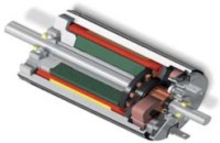
DC Motor
From the start, DC motors seem quite simple. Apply a voltage to both terminals, and weeeeeeee it spins. But what if you want to control which direction the motor spins? Correct, you reverse the wires. Now what if you want the motor to spin at half that speed? You would use less voltage. But how would you get a robot to do those things autonomously? How would you know what voltage a motor should get? Why not 50V instead of 12V? What about motor overheating? Operating motors can be much more complicated than you think.

Voltage
You probably know that DC motors are non-polarized - meaning that you can reverse voltage without any bad things happening. Typical DC motors are rated from about 6V-12V. The larger ones are often 24V or more. But for the purposes of a robot, you probably will stay in the 6V-12V range. So why do motors operate at different voltages? As we all know (or should), voltage is directly related to motor torque. More voltage, higher the torque. But don't go running your motor at 100V cause thats just not nice. A DC motor is rated at the voltage it is most efficient at running. If you apply too few volts, it just wont work. If you apply too much, it will overheat and the coils will melt. So the general rule is, try to apply as close to the rated voltage of the motor as you can. Also, although a 24V motor might be stronger, do you really want your robot to carry a 24V battery (which is heavier and bigger) around? My recommendation is do not surpass 12V motors unless you really really need the torque.
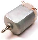
El-Cheapo DC Motor

Current
As with all circuitry, you must pay attention to current. Too little, and it just won't work. Too much, and you have meltdown. When buying a motor, there are two current ratings you should pay attention to. The first is operating current. This is the average amount of current the motor is expected to draw under a typical torque. Multiply this number by the rated voltage and you will get the average power draw required to run the motor. The other current rating which you need to pay attention to is the stall current. This is when you power up the motor, but you put enough torque on it to force it to stop rotating. This is the maximum amount of current the motor will ever draw, and hence the maximum amount of power too. So you must design all control circuitry capable of handling this stall current. Also, if you plan to constantly run your motor, or run it higher than the rated voltage, it is wise to heat sink your motor to keep the coils from melting.

Power Rating
How high of a voltage can you over apply to a motor? Well, all motors are (or at least should be) rated at a certain wattage. Wattage is energy. Innefficieny of energy conversion directly relates to heat output. Too much heat, the motor coils melt. So the manufacturers of [higher quality] motors know how much wattage will cause motor failure, and post this on the motor spec sheets. Do experimental tests to see how much current your motor will draw at a desired voltage.
The equation is:
Power (watts) = Voltage * Current

Power Spikes
There is a special case for DC motors that change directions. To reverse the direction of the motor, you must also reverse the voltage. However the motor has a built up inductance and momentum which resists this voltage change. So for the short period of time it takes for the motor to reverse direction, there is a large power spike. The voltage will spike double the operating voltage. The current will go to around stall current. The moral of this is design your robot power regulation circuitry properly to handle any voltage spikes.

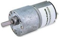
Geared DC Motor

Torque
When buying a DC motor, there are two torque value ratings which you must pay attention to. The first is operating torque. This is the torque the motor was designed to give. Usually it is the listed torque value. The other rated value is stall torque. This is the torque required to stop the motor from rotating. You normally would want to design using only the operating torque value, but there are occasions when you want to know how far you can push your motor. If you are designing a wheeled robot, good torque means good acceleration. My personal rule is if you have 2 motors on your robot, make sure the stall torque on each is enough to lift the weight of your entire robot times your wheel radius. Always favor torque over velocity. Remember, as stated above, your torque ratings can change depending on the voltage applied. So if you need a little more torque to crush that cute kitten, going 20% above the rated motor voltage value is fairly safe (for you, not the kitten). Just remember that this is less efficient, and that you should heat sink your motor.

Velocity
Velocity is very complex when it comes to DC motors. The general rule is, motors run the most efficient when run at the highest possible speeds. Obviously however this is not possible. There are times we want our robot to run slowly. So first you want gearing - this way the motor can run fast, yet you can still get good torque out of it. Unfortunately gearing automatically reduces efficiency no higher than about 90%. So include a 90% speed and torque reduction for every gear meshing when you calculate gearing. For example, if you have 3 spur gears, therefore meshing together twice, you will get a 90% x 90% = 81% efficiency. The voltage and applied torque resistance obviously also affects speed.
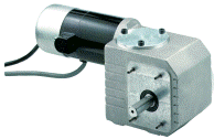
Right Angle DC Motor

Control Methods
The most important of DC motor control techniques is the H-Bridge. After you have your H-Bridge hooked up to your motor, to determine your wheel velocity/position you must use an encoder. And lastly, you should read up on good DC Motor Braking methods.

Other Information
Place small microfarad capacitors across motor leads to extend motor life. This works really well with noisy and other el-cheapo motors, almost doubling motor life. However there is much less improvement using this technique with the more expensive higher end motors. For a more advanced method on how to choose a motor for your specific robot, check out my tutorial on robot dynamics.